
Reduce noise from air inlets
Noise problems at residential air inlets: airflow noise, insulation against external noise, practical advice, simulations
Jean Boulvert et Gabriel Gormezano
1/17/202510 min read
Article written in collaboration with Gabriel Gormezano, Econology, a French company selling building ventilation equipment online.
Residential air inlets can cause noise problems, either by letting outside noise in, or by generating noise as the air flows through them.
Acoustic performance, particularly against external noise, depends on the model of air inlet accessory.
This article deals with the acoustic aspects of air inlets, and offers solutions to noise problems emanating from them.
I. Generalities
Air inlets, also known as vents, play an essential role in the supply of fresh air, whether for natural ventilation or single-flow ventilation systems.
They consist of an opening in the building envelope and various accessories. This opening is most often integrated into the window sash and/or frame, or into the roller shutter casing. More rarely, they are made directly through the wall.
A “bare” opening is not ideal, as it cannot effectively control airflow.
To regulate this flow and guarantee an optimum quantity of fresh air, a device called an “air inlet” is installed inside, as an extension of the opening. Air inlets can be of several types: fixed, humidity-sensitive or self-regulating. Humidity-controlled models adjust the airflow according to the humidity level in the home, increasing the flow when humidity is high. Self-adjusting models, on the other hand, maintain a constant flow rate, relatively unaffected by atmospheric variations.
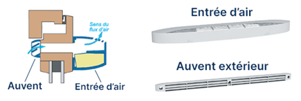
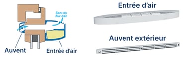
On the outside, another element, often called a “canopy” or “deflector”, is positioned in line with the opening. Its main function is to protect the opening from rainwater.
Air inlets can be linked to two noise problems with distinct origins and solutions:
The flow of air through the air inlet can generate noise, such as whistling or wind noise.
Outside noise (road traffic, airplanes, downtown activities, etc.) enters the home via the opening in the building envelope. A bit like leaving a window ajar. This is a noise problem independent of airflow.

II. Airflow noise
When an air stream (wind) flows through a small-diameter duct or encounters obstacles, it produces noise. The higher the velocity of this flow, the greater the sound intensity.
Air inlet accessories are designed to minimize the noise generated by airflow. However, when airflow velocity exceeds the specified operating range, it becomes difficult to completely eliminate this noise nuisance. Moreover, there are no standardized indicators for assessing the performance of different models in terms of airflow noise reduction.
In the event of airflow noise, the first step is to dismantle the accessories and clean both the opening and the components themselves. Regular maintenance, ideally once or twice a year, will not only reduce this noise, but also improve indoor air quality by facilitating the inflow of fresh air.
When reassembling, it is essential to ensure that the accessories are correctly aligned with the window or wall opening. Incorrect alignment can create gaps, leading to whistling.
If the noise persists, whether or not there's wind outside, it's time to check the overall balance of the ventilation system. For example, if a CMV extracts 200 m³/h of air while the dwelling has only one air inlet calibrated for 45 m³/h, this will result in an imbalance. The airflow will have to force its way through this opening, exceeding the flow limits provided for. This phenomenon is particularly common if the CMV is oversized, operates at a high flow rate, or if, in an apartment building, some residents have blocked their extract units or air inlets. In such cases, the air missing from the blocked units is redistributed to those still ventilated, resulting in overflow, noise pollution and increased heat loss, leading to higher energy costs. In such cases, it is advisable to report the problem to the condominium manager, so that other occupants can be made aware of the problem.
To find out more about the effects of blocked air inlets and outlets in apartment buildings, visit: https://www.econology.fr/le-blog/perte-de-charge-reseau-ventilation.
If the whistling persists after cleaning and balancing the ventilation system, but disappears when the accessories are removed, it may be necessary to replace the air inlet. The internal components of humidity-sensitive or self-regulating air inlets, such as the tabs, can wear out over time and lose their effectiveness. Before investing in new equipment, you can test an inversion between two air inlets in your home to see if the problem persists.
Changing the awning for a model with a different shape can also be effective if the whistling occurs in strong winds.
III. Exterior noise
A. Façade insulation
Exterior noise can enter a home through its entire envelope: walls, windows, roof, air inlets, etc. However, the ability of these elements to limit noise transmission is not uniform. However, the ability of these elements to limit noise transmission is not uniform. It varies according to several factors, such as their dimensions, the materials used, their thickness, their assembly and associated accessories. For example, if a window fitted with an air intake has no seals between the frame and sash, or if it closes poorly, it is likely to be the main weak point in the façade's acoustic insulation.
To effectively reduce noise inside the home, you need to maximize “façade insulation”. This means striking a balance between the acoustic performance of each envelope element, including air inlets. Particular attention must be paid to the level of external noise to which the dwelling is exposed, in order to correctly size the insulation required. Current acoustic standards impose minimum performance levels to be achieved, depending on the level of noise exposure.
For more details and examples of acoustic solutions, please consult this document: https://www.bruit.fr/images/stories/pdf/exemples_solutions_acoustiques.pdf.


In practice, in an older, non-renovated home, improving the acoustic insulation of air inlets will rarely improve the insulation of the facade.
Conversely, in a renovated or new home, with good-quality, well-installed windows and walls that may have been thermally (and consequently acoustically) insulated, air inlets are often the weak point in façade insulation. It would be counterproductive to install soundproof glazing while leaving a non-acoustically insulated opening right next to it!
B. Acoustic performance of air inlets as a function of frequency
The acoustic insulation of an air inlet, whether or not equipped with an accessory, can be measured in the laboratory in accordance with standard NF EN 13141-1. The higher the sound insulation value, expressed in decibels (dB), the better the air inlet blocks external noise.
For these tests, the air inlet is installed on a dense 60 mm thick wall separating two rooms. A diffuse acoustic field (representing noise from all directions) is generated in one of the rooms. Sound insulation is then determined by measuring the ratio between the incident sound power in the transmitting room and that transmitted to the receiving room. This frequency-dependent result is expressed in dB. The calculation takes into account a virtual surface area of 10 m², equivalent to an air inlet mounted on an almost perfectly insulating wall of the same surface area.
The graph below illustrates the acoustic insulation of an air inlet in three different configurations:
Without accessory (single opening 172 × 2 × 12 mm²): black line.
Equipped with Aldes EA45 air intake: green dotted lines.
Equipped with Aldes EHL-L air inlet: dotted orange lines.
The data come from measurements carried out at CETIAT and numerical simulations performed by Sil&Add.
In the case of an opening without accessories, sound insulation remains relatively constant between 100 Hz and 1000 Hz, but decreases sharply from 2500 Hz onwards. This is due to the longitudinal half-wave resonance of the 60 mm long opening. The frequency of this resonance is inversely proportional to the length of the opening.
With Aldes EA45 and EHL-L accessories, sound insulation is significantly improved compared with a simple opening. In particular, around 2500 Hz, insulation is more effective thanks to the damping of longitudinal resonance by these devices. What's more, the acoustic insulation offered by the EHL-L exceeds that of the EA45 by around 5 dB in the frequency range from 1000 Hz to 3150 Hz, demonstrating better acoustic performance.
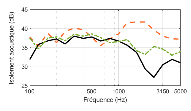

Acoustic insulation of an air inlet without accessories (black), equipped with an Aldes EA45 air inlet (green dotted line), and equipped with an Aldes EHL-L air inlet (orange dotted line).
C. Unique sound insulation performance indices for air inlets
To make it easier to assess the acoustic performance of air inlets, unique, frequency-independent indices are used. These indices, comparable to those used for wall and window insulation, are calculated in accordance with standard NF EN ISO 717-1. The calculation is based on comparing the sound insulation curve (between 100 and 3150 Hz) of the air inlet with a reference curve. Two air inlets with the same insulation index may exhibit different acoustic behaviour at different frequencies.
The main indicator used is Dn,e,w (C ; Ctr).
Dn,e,w (Ctr) = Dn,e,w + Ctr. This corresponds to the sound insulation of an air inlet against A-weighted traffic noise. This indicator is particularly suitable for assessing performance in the face of typical outdoor noise, such as road, rail or building site traffic.
Dn,e,w (C) = Dn,e,w + C. It measures insulation against A-weighted pink noise. Often supplied by manufacturers, it reflects performance against higher-pitched noises, such as voices or sounds produced by a television, or the shouts of a playground.
The higher the index value, the more effectively the air intake insulates against external noise.
Applying standard calculation methods, we obtain the following values:
Without accessories :
Dn,e,w (C) = 32 dB
Dn,e,w (Ctr) = 34 dB
Aldes EA45 :
Dn,e,w (C) = 35 dB
Dn,e,w (Ctr) = 36 dB
Aldes EHL-L :
Dn,e,w (C) = 39 dB
Dn,e,w (Ctr) = 39 dB
These indices reflect the differences observed on the frequency isolation curves.
D. Simulation of air inlet insulation
To illustrate these performances in concrete terms, acoustic simulations have been carried out. These simulations are based on a hypothetical configuration where only the air inlet influences sound transmission.
In reality, external noise also penetrates through other elements of the façade (walls, windows, etc.), and interacts with the interior of the dwelling (absorption by furniture, room resonances, etc.). However, this fictitious configuration is close to standard laboratory test conditions. The calculations are based on the insulation curves presented above.
The scenario simulates five cases of noise transmission:
Direct, unimpeded transmission: raw noise transmitted directly from transmitter to receiver.
Transmission via accessory-free opening.
Transmission via an opening equipped with an Aldes EA45 air inlet.
Transmission via an opening equipped with an Aldes EHL-L air inlet.
Transmission via an opening equipped with an Aldes EHL-L and an Aldes acoustic canopy.
Two types of noise were considered:
Noise produced by a heat pump outdoor unit.
The sound of a car passing close to a playground.
These simulations can be used to quantify and visualize the sound insulation gains made by different equipment, providing a better understanding of performance in real-life situations.


IV. Air inlet insulation
The classic configuration is a joinery-mounted air intake combined with a standard canopy.
Depending on the model, the sound insulation value Dn,e,w (Ctr) is then between 34 dB and 39 dB. An air intake is considered “acoustic” from 36 dB upwards.
Accessories are available to increase sound insulation up to 42 dB, while maintaining the same joinery installation. This increase in insulation is not negligible, as shown in the videos above.
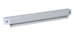
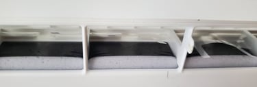
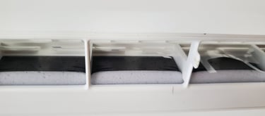
A. Acoustic extension / spacer
It is positioned between the mounting wall and the air intake. It therefore increases the length and visibility of the air inlet inside the home. Only certain air inlet models are compatible with this accessory.

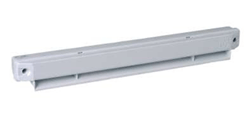
B. Acoustic canopy / outer cap
Replaces the standard canopy. Although bulkier than the standard awning, it is installed externally to increase sound insulation without being visible from inside the home.
Accessories (extension/acoustic spacer and acoustic external canopy) reduce airflow very slightly. If an air inlet is advertised as compatible with one or more accessories, this implies that its nominal flow rate is not affected. In other words, the complete device meets the same normative requirement for announcing a flow rate value. To ensure this, manufacturers have laboratory tests carried out on air inlets alone and in combination with accessories sold as compatible.
C. Insulation values
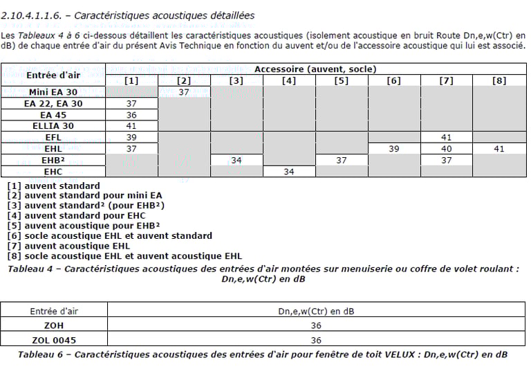
Extracts from Avis Techniques for the Anjos and Aldes joinery air inlet range are reproduced below. They are available in full on the CSTB website.
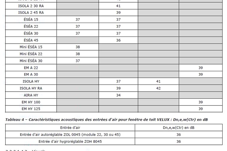
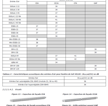
Extract from technical advice 14.5/17-2275_V4 presenting Dn,e,w (Ctr) values for Anjos joinery air inlets --> Click to view full screen
Extract from technical advice 14.5/17-2266_V6 presenting Dn,e,w (Ctr) values for Aldes joinery air inlets --> Click to view full screen
D. Wall-mounted air inlets
Wall-mounted air inlets provide better insulation than wall-mounted air inlets. They are, however, more complicated to install and less discreet on the façade.
Depending on the model of wall-mounted accessory and air inlet, the Dn,e,w (Ctr) sound insulation value is between 46 dB and 57 dB.
V. Improving air inlet insulation
Obstructing an air intake with paper, foam or plate is strongly discouraged. This disrupts the essential balance between incoming and outgoing air in a dwelling. Air inlets are designed to guarantee a calibrated flow (22, 30 or 45 m³/h), and their number and location comply with standards. Obstructing an air inlet can unbalance the ventilation network, creating problems of air pollution, humidity and noise on other inlets and extract units - see II. Airflow noise.
The only time an air intake can be blocked is when the ventilation system has been modified. For example, changing from natural ventilation to CMV. This type of modification must be carried out in accordance with current regulations.
Solutions to improve sound insulation of air inlets without compromising ventilation
Cleaning accessories and air inlet opening
Follow manufacturers' recommendations for regular maintenance (1-2 times a year).
Acoustic foam elements must be free of pollution deposits. In the event of serious damage or insufficient cleaning, replace only the acoustic foam.
Replacement with a model offering superior sound insulation
Opt for an air intake with increased insulation (by several dB).
Nominal flow reduction (if authorized)
If regulations allow, replace a 45 m³/h air intake with a 30 m³/h one.
Wall feed-through installation
Replace joinery air inlets with wall penetrations. Although this solution is highly effective, it requires more complex installation.
The table below summarizes the impact of various actions to increase the insulation value of air inlets.